


Build a small version of a foosball table
The foosball table must be fully functional
The design should be as fancy as possible
Individual steps are to be made with the 3D printer or the CNC mill
The basic idea for the look comes from my project Design Laptop Holder
The other inspiration afforded the Allianz Arena in Munich.

A oval body I had seen often, an oval playing area until now not yet. Similarly, the kicker should be illuminated not only from above and below, but also in individual layers on the side of the kicker. But most ideas came to me during the preparation itself.
Material Dimensions
acrylic white acrylic red and yellow
beech multiplex 18mm
round steel 9mm
brass sleeves
Balsa wood
RGB cable 6,3mm
toggle wire
wooden balls a
crylic transparent
timber section
semicircle
acrylic black
Tools needed
Cordless Screwdriver
circular saw
Drilling Machine
router
soldering iron
Files and rasps
Abrasive paper and sanding corks
Various drills
CNC milling machine
Screw
1 planning


Design foosball table design and milling file end part design and milling file end portion gate design ball return
Since I had no building instructions, I had to build the most complete out of my imagination out. I had thus indeed always problems in the later stages, but on the whole it has worked quite well.
In advance I had formed only a handful of plans.
These related mainly to the optics of the foosball table.
2 body


End part with cut-out for the subsequent gate end part during the milling
The complete corpus consists of 40 items made of wood joined together. At the beginning I wanted to make all the parts with the router and end mills. Due to the accuracy but I opted for the CNC milling machine.
Pro Part I needed about 25 minutes!
The side parts, I then cut with a circular saw to size.
3 Basic body with first adjustments


First, the wedge to the proper length and width saws. A diagonal line, mark, and all with double sided tape attach to a bar.
The bar functions here as auxiliary tool, see more images. The shape of the wedge with the circular saw. Pavers Rolling then hone down with the belt sander.
Since the body seemed much too bold, I decided to leave the top ring taper expire.
In addition I have made with the circular saw and the belt sander four wedges.
4 Base with further adjustments (rounding)

Since the body was still too heavy, needed a further adjustment. I decided with an ogee edit each second layer and round off only the end parts and the splines on the top ring.
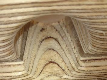
5 basic body with further adjustments (acrylic coating)
finished machined part finished machined part.


Quite pleased I still was not and so I had the idea between each rounded layer, a layer of transparent acrylic to set.
For the preparation I have taken the milling files of the end pieces. These have been reduced by only a few millimeters in order to adapt to the rounded parts.
Actually I wanted to do entirely without screws in the production, but this had to attach the side parts for safety yet.
During this phase, I came with the idea of lighting.
6 The first tests with LEDs


Initial trials with a pointer. The result was really good. It was followed by further tests with a RGB strip. As already said, I had during this preparation phase, the idea with the lighting.
I made the first experiments with a laser pointer and later with an RGB band that I bought on Ebay.
7 Manufacture of the bottom plate and the court


The finished ring on the acrylic glass plate and then repeating that inner form with a pen.
Laying PREV the finished ring on the acrylic glass plate and then repeating that inner form with a pen. The markings enlarge a 10 mm. Saw out the shape and reprocess. With a jigsaw, the recesses are mounted for goal. In the production of the plates I have a finished ring required. How I built this, you see the next step.
8 Connect individual components together


A bar is screwed, the items are aligned and coated with gum. Subsequently, the other bar is fixed with a screw, the bar is then pressed and screwed into the ring.
Auxiliary device for glueing. A bar is screwed, the items are aligned and coated with gum. Subsequently, the other bar is fixed with a screw, the bar ... After milling can well recognize the inner milled groove. In this, the acrylic glass plate is placed. Fits perfectly! Fits perfectly!
As already mentioned I really wanted to use any screws.
Therefore, almost the entire football is stuck with all adhesives.
If you follow the instructions, which works perfectly.
For the production itself I built a makeshift.
In this one can insert the items, align and glue under tension.
The individual rings in turn are bonded together by means of clamps or glued.
In the bottom and middle ring I each milled with a disc groove a 10 mm wide groove. In this are later the respective acrylic sheets.
9 ball throw and ball ball
ball throw ball throw lit

This step must be done before assembling.
The ball is kept relatively simple, I refer to the respective rings secured with clamps and drilled with a Forstner bit.
In the ejection I addition, rounded by means of a wedge, a small slope with built-in and the outer edges with a ogee.
10 Manufacture of feet


The feet are glued to the body. Later on they are adapted to the double thickness!
The feet are cut only from measure and at the end faces the desired miter shall be affixed.
Fixed they are only with glue on the body - holds bombproof!
In the course I decided feet double as to make wide. But had the problem that I already switch and Co. had installed, which were now in the way. Therefore, I have incorporated a small notch at a distance, but does not alter the stability.
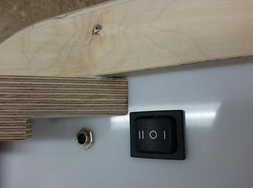
11 providing the switch and the 6.2 mm jack


Hole for the 6.2 mm jack. fix socket of interior with a flat nut. Jack checked for proper functioning. Recess for the toggle switch. arriving position, pre-drill with a small drill bit along the rim, adjust recess with a key file. Toggle inserting.
For 6.2 mm jack, I have decided for aesthetic reasons. When the toggle switch, it was important that this has two stages. In the first stage only the battery to be charged, at the second stage is only the illumination function.
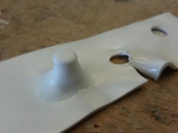
12 manufacturing the ball retrace


Acrylic tube in half and turn a screw in shape. Then fix it with a hot glue gun on the carcass. illuminated ball return already. Pavers ball return already illuminated.
In order not to interrupt the light from the LED's unnecessary, I have decided to build the complete ball return of transparent acrylic glass. The individual parts were glued with a special plastic adhesive.
The ball return is in the middle at the same time as a support for the court.
13 Installation art
Band is laid in the corpus. Wiring wiring wiring wiring


As already described, there are two functions.
Firstly, the loading and on the other hand, the illumination.
The tape was attached by double-sided tape on the body and on the return to the kicker illuminate optimally. The band has a length of 5 m and has built an integrated receiver. This allows me the tape in the closed state, with a remote control, to use and thus to change the colors. Establishments is the kicker with a little gel battery from an old wheelchair.
14 Yard Line

The pitch mark is placed below the playing surface and is made of black acrylic which was fastened with plastic adhesive to the plate.
15 Ball Catch


wire around a bend roundwood. Bend In 90 degree angle. The ends to length. arrive later position, drill and glue.
The ball catcher I bent from a 3mm Straken wire.
To fix I, left and right, drilled small holes next to the ball throw and the wire then adhered.
16 counter


Rod to length and bend the ends at a 90 degree angle. Subsequently, the wire around an end part bent in order to obtain the appropriate rounding. 24 balls black paint and carefully slide onto the wire. Align counter in the correct position. arrive holes and transferred to the second part. Drill and fix then counter with glue.
The counter I also bent from a 3 mm thick wire. The balls I have from an old car seat cover.
17 holes for the through rods


Drill the holes. First tests with wooden sticks. Side panels with holes already installed and inlaid brass casings in wood. Metal rods, their position accordingly, cut to length.
This step was by far the hardest and has given me a lot of problems. Due to the special size of my foosball table, I unfortunately could not use conventional ball bearings.
At the first attempt I have the holes and attached to thread the 10mm wide bars tried. Since the holes are not perfect curse ended in today, this has not worked.
On the second attempt I have further drilled holes. Although I could thread the rods, but the friction between metal and wood was simply too great.
At the third attempt I made my brass sleeves and pressed into the wood. The result has not pleased me. At the fourth attempt, I wiped the sleeves, but the result was still not satisfactory. After a long search I have found a dealer who sold me, very low, 9mm round bars. Thus I was able to escape the inaccurate balance to achieve better lubricity with the brass.
18 Handles and end caps


Drill and tape the handle. The handles painted black. Acrylic heat and the rods push in (deep drawing). Cap and saw off paint.
For the handles I have made it very easy. These consist of normal files folders that were painted.
The end caps I made of acrylic glass.
19 Posts and crossbar


This step was relatively painless.
Cut semicircle material, miter and glued. the whole is then painted black and glued to the body.
20 pawns


Base material to long strips from sticking together. Strip cut into suitable blocks. Game characters from the blocks milling. Pawns grind, arriving hole and then drill and chamfer.
With the game characters I wanted to pick up on the optics of the foosball table again. In addition I have colorful acrylic glass and balsa wood cut into strips, then glued together in layers, cut into small blocks and milled the pawns.
21 Mount pawns


Aligning the players. Players take on the bars and align it.
First, I have the figures simply placed in different formations.
Decided I was then for a 1-2-3 system, so very offensive: D.
The players are then drawn to the poles, aligned and glued.
As the buffer I have attached to the respective outermost players, small grommets from the automotive sector.
22 Conclusion
The table is not the burdens of a normal Kickers withstands is clear to me, but that he should never.
It is fully functional and is intended only to demonstrate what you can build everything with a little creativity.
What you might not see directly, is the long construction period.
I required more than 200 hours for the kicker.
For each step, several prototypes were mostly made and the processes repeatedly tried before I went to the original. The body was completely hand slept at the transitions between the individual parts perfectly. This grinding work have probably takes up a third of the total time: D
The whole effort but definitely worth it!
23 The result


We highly recommended wood project resource which will you to simply make wood project yourself. Enter Access 16000 Woodworking Plans


0 comments:
Post a Comment